TM 9-2350-261-34
N O T E
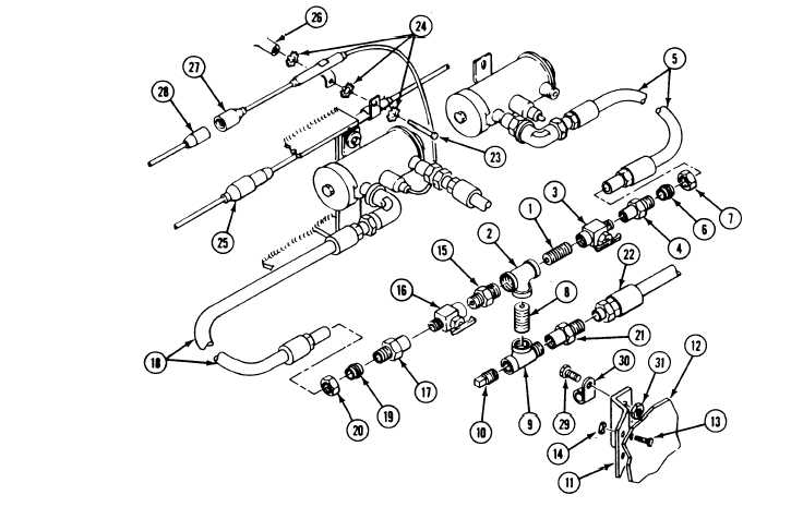
Parts (1) through (15) and (29, 30, and 31)
are already installed if the electronic
equipment heater has been installed.
86. Install
87. Install
88. Install
89. Install
Secure
90. Install
91. Install
92. Install
93. Install
Secure
94. Install
95. Install
nipple (1) in tee (2).
shutoff cock (3) on nipple (1).
adapter (4) in shutoff cock (3).
fuel hose (5) in adapter body (4).
with sleeve (6) and nut (7).
nipple (8) in tee (2).
tee (9) on nipple (8).
plug (10) in tee (9).
bracket (11) on fuel hose guard (12).
with two screws (13) and nuts (14).
adapter (15) in tee (2).
coolant heater fuel shutoff cock (16)
on adapter (15).
96.
97.
98.
99.
100.
101.
102.
103.
Install adapter body (17) on coolant heater
fuel shutoff cock (16).
Install fuel hose (18) in adapter body (17).
Secure with sleeve (19) and nut (20).
Install adapter body (21) in tee (9).
Connect fuel hose (22) to adapter
body (21).
Remove screw (23), lockwasher (24), and
personnel heater fuel pump lead (25) from
weldnut (26).
Install coolant heater fuel pump lead (27)
and personnel heater fuel pump lead (25)
on weldnut (26). Secure with screw (23)
and three lockwashers (24).
Connect circuit 400C lead (28) to coolant
heater fuel pump lead (27).
Install adapter (15) on bracket (11). Secure
with screw (29), clamp (30), and nut (31).
GO TO NEXT PAGE
14-27