TM 9-2350-261-20-2
R E P A I R L E F T / R I G H T S T E E R I N G L E V E R S
D E S C R I P T I O N
This task covers:
Remove (page 23-7).
Clean, Inspect, and Replace (page 23-8).
Install (page 23-8).
INITIAL SETUP
Tools:
Personnel Required:
General Mechanics Tool Kit (Item 30, App D)
Unit Mechanic
Snap Ring Pliers (Item 45, App D)
Socket Wrench Set (Item 89, App D)
References:
Torque Wrench (Item 95, App D)
see your -lo
Materials/Parts:
Self-locking nut (2)
Self-locking nut (2)
Self-locking nut (2)
Spring pin (3)
Equipment Conditions:
Engine stopped/shutdown (see your -10)
Carrier blocked (see your -10)
Driver’s seat removed (page 24-127)
1.
2.
R E M O V E
4.
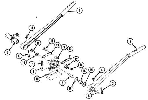
Place right and left steering levers (1 and 2)
5.
full forward, in released position.
Remove screw (3), locknut (4), and left steer-
ing lever (2) from cross-shaft (5). Remove
6.
woodruff key (6) from cross-shaft. Discard
locknut.
7.
N O T E
The same number of shims removed will
be installed.
3. Remove two screws (7), washers (8), bracket
(9), and shims(10) from driver's floor plate.
Remove bracket (9) from cross-shaft (5).
Remove two screws (11), two stop levers (12),
two quadrants (13) and two locknuts (14)
from bracket (9). Discard locknuts.
Remove two retaining rings (15), one bearing
(16) from inside bracket (9).
Remove screw (17), locknut (18), and right
steering lever (1) from cross-shaft (5).
Discard locknut.
GO TO NEXT PAGE
23-7