6.
7.
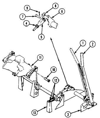
Lock steering levers (1 and 2) in front notch
of quadrant (3).
Loosen two jamnuts (4) and turn two clev-
8.
9.
10.
11.
12.
13.
ises (5) until clevis holes align with steering
lever cross-shaft (6) holes.
N O TE
Before installing clevis pin through clevis
and cross shaft levers, ensure stoplight
switch lever is on proper side of linkage
tabs (the side toward front of vehicle)
then check and adjust stoplight switch if
necessary (page 12-132).
Install clevises (5) to steering cross-shaft
(6). Secure with two clevis pins (7), washers
(8), and new cotter pins (9).
Tighten two jamnuts (4).
Remove two screws (10) from differential
brake levers (11). Release steering lever to
full forward position.
Connect two return springs (12) to
brackets (13).
Install linkage access covers (page 23-10).
Install air cleaner housing and element
(page 7-7).
FOLLOW-THROUGH STEPS
1. Perform differential brake adjustment
4.
(page 21-18).
5.
2. Close power plant front access door and raise
trim vane (see your -10).
6.
3. Install driver’s power plant access cover
(page 24-25).
7.
Connect battery ground leads (page 13-2).
Raise and lock ramp (see your -10).
Unlock steering levers. Operate earner to
check that steering brakes operates properly.
Stop/shutdown engine (see your -10).
END OF TASK
23-3
TM 9-2350-261-20-2