TM 9-2350-261-20-2
A D J U S T V O L T A G E R E G U L A T O R ( 1 0 0 / 2 0 0 A M P G E N E R A T O R)
INITIAL SETUP
Tools:
References:
General Mechanics Tool Kit (Item 30, App D)
See your -10
Digital Multimeter (Item 43, App D)
TM 9-6140-200-14
TM 9-2350-300-20-1
Personnel Required:
Unit Mechanic
Equipment Conditions:
Engine stopped/shutdown (see your -10)
Carrier blocked (see your -10)
ADJUST
5.
N O T E
6.
Check batteries to make sure they are
fully charged (see TM 9-6140-200-14).
R e f e r t o
TM9-2350-300-20-1
for
adjustment procedures for M741A1 with
M163A1 weapon system installed.
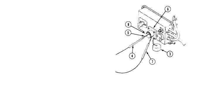
1. Remove access screw (1) from regulator (2).
Remove receptacle cap (3).
Place red lead (4) in positive socket of NATO
plug (5) on auxiliary power (slave) receptacle
(6). Touch negative lead (7) to outside of
NATO plug (8) on receptacle.
N O T E
On carriers that have standard auxiliary
power receptacles touch red lead to
positive and black lead to negative
sockets in the receptacle.
2. Start engine and allow to run for about 20
minutes with service headlights on
(see your -10).
3. Turn off service headlights.
4. Set multimeter to read voltage on the
50V DC scale.
9-38
Change 1