TM 9-2350-261-34
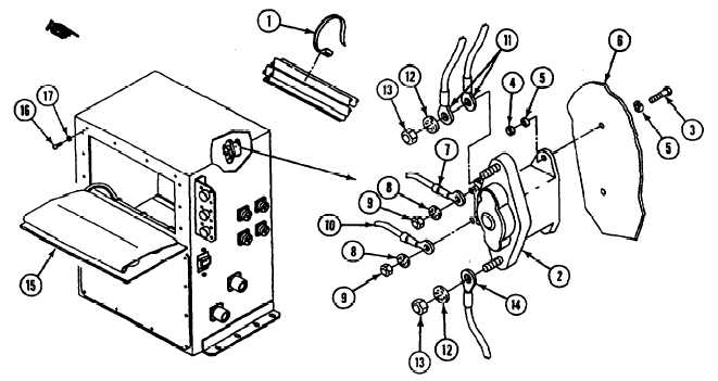
56. Secure leads with new straps (1) as
required.
60. Install leads 31B and 31C (11),
lockwashers (12), and nut (13) on terminal
57. Install relay K6 (2), two screws (3), new
locknuts (4), and four washers (5) on rear
panel (6).
A2 of relay K6 (2).
61. Install lead 31A (14), lockwasher (12), and
nut (13) on terminal Al of relay K6 (2).
58. Install lead 32Q (7), lockwasher (8), and
nut (9) on terminal X2 of relay K6 (2).
62. Close faceplate (15) and install ten
screws (16) and new lockwashers (17).
59. Install lead 44A (10), lockwasher (8), and
nut (9) on terminal X1 of relay K6 (2).
FOLLOW-THROUGH STEPS
1. Install power control enclosure assembly
see your -20).
END OF TASK
21.1-38
Change 4

