TM 9-2350-261-34
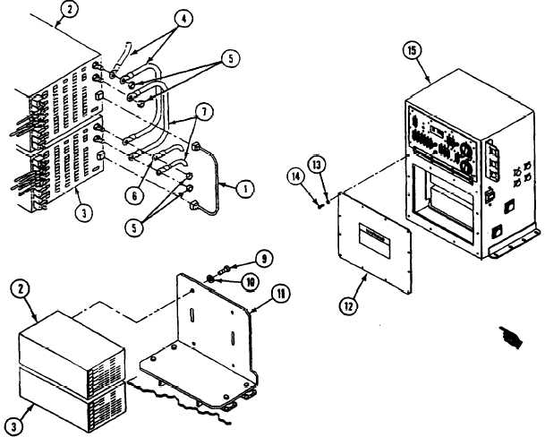
18. Connect jumper cable (1) to J1 on power
supply (2) and J1 on power supply (3).
19. Connect circuits 31E and 31D (4) leads with
nut (5) to positive terminal of power
supply (2).
20. Connect circuits 31C (6) and 31D (4) leads
with nut (5) to positive terminal of power
supply (3).
21. Connect circuits 32D and 32E (7) leads with
nut (5) to negative terminal on power
supply (3).
22. Connect circuit 32D (7) with nut (5) to neg-
ative terminal of power supply (2).
23. Secure power supply (2) with four screws (9)
and new lockwashers (10) on bracket (11).
24. Secure power supply (3) with four screws (9)
and new lockwashers (10) on bracket (11).
25. Install cover (12) on enclosure (15). secure
with 12 new lockwashers (13) and
screws (14).
FOLLOW-THROUGH STEPS
1. Install power control enclosure assembly
(see your -20).
END OF TASK
Change 4
21.1-41