TM 9-2350-261-34
REPAIR SIGNAL PATCH PANEL BOX A10 (M1068 ONLY)
DESCRIPTION
This task covers: Disassemble (page 21.1-42).
Clean, Inspect, and Repair (see Chapter 2).
Assemble (page 21.1-44).
INITIAL SETUP
Tools:
Electronic Equipment Tool Kit
(Item 94.1, App B)
Materials/Parts:
Sealing compound (Item 74.1, App C)
Sealing compound primer (Item 72.1, App C)
Lockwasher (as needed)
Locknut (20)
Rivet (as needed)
Personnel Required:
Radio Repairer 29E10
References:
See your -20
Equipment Conditions:
Signal patch panel box removed
(see your -20)
DISASSEMBLE
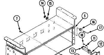
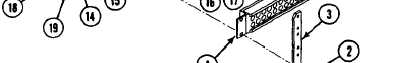
1. Remove twelve screws (1), lockwashers (2),
two strips (3), and three jackfields (4) from
signal patch panel box (5).
NOTE
Tag all wires/leads before removal, use
wiring diagram (page 21.1-43).
2.
3.
4.
5.
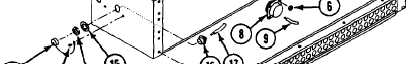
6. Remove jamnuts (14), lockwashers (15), and
eight connectors (16) from signal patch panel
box (5).
7. Remove wires (17) from eight connectors (16).
8. If dust caps (18) are damaged, remove
rivets (19) and dust caps from signal patch
panel box (5).
Remove twenty locknuts (6), screws (7), and
five connectors J135,J136,J138,J139, and
J140, (8) from signal patch panel box (5).
Discard locknuts.
Disconnect wires (9) from five connectors
J135, J136, J138, J139, and J140 (8).
Remove screws (10), lockwashers (11), and
156 jacks (12) from three jackfields (4).
Discard lockwashers.
Remove two leads (13) from each jack (12).
21.1-42
Change 4