TM 9-2350-261-34
NOTE
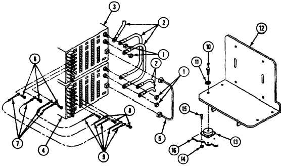
Tag all leads before disconnecting from
terminals.
4. Remove four nuts (1) and five leads (2)
from two power supplies (3 and 4).
5. Disconnect jumper cable (5) from two power
supplies (3 and 4).
6. Remove three screws (6) and four leads (7)
from power supply (3). Lift power supply (3)
from enclosure, have helper assist.
7. Remove three screws (8) and five leads (9)
from power supply (4). Lift power supply
from enclosure, have helper assist.
8. Remove four screws (10), lockwashers (11),
and bracket (12) from four isolators (13).
Discard lockwashers.
9. Remove 16 locknuts (14), screws (15), and
four isolators (13) from enclosure (16).
Discard locknuts.
INSTALL
10. Install four isolators (13), 16 screws (15),
and new locknuts (14) in enclosure (16).
11. Install bracket (12), four new
lockwashers (11), and screws (10) on four
isolators (13).
12. Lift power supply (4) into enclosure, have
helper assist. Install circuits 10A and 10B
leads with screw (8) on AC HIGH terminal
of power supply (4).
13. Install circuits 8B and 8C leads with
screw (8) on AC LOW terminal of power
supply (4).
14. Install circuit 3Z lead with screw (8) on
GND terminal of power supply (4).
15. Lift power supply (3) into enclosure, have
helper assist. Install circuit 10B lead with
screw (6) on AC HIGH terminal of power
supply (3).
16. Install circuit 8C lead with screw (6) on AC
LOW terminal of power supply (3).
17. Install circuits 3Z and 3Y leads with
screw (6) on GND terminal of power
supply (3).
21.1-40
Change 4