TM 9-2350-261-34
23.
24.
25.
26.
27.
28.
29.
30.
31.
Disconnect lead 15A (1) from terminal A2 of
contactor RC1 (2).
Disconnect leads 8A, 8D, and 8E (3) from
terminal L2 of contactor RC1 (2).
Disconnect leads 8G and 8E (4) from
terminal Al of contactor RC1 (2).
Disconnect leads 9A, 9B, and 9C (5) from
terminal L1 of contactor RC1 (2).
Disconnect lead 13D (6) from terminal 51 of
contactor RC1 (2).
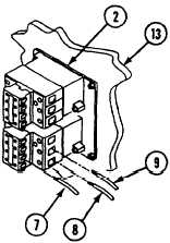
Disconnect lead 14A (7) from terminal 52 of
contactor RC1 (2).
Disconnect lead 17A (8) from terminal T1 of
contactor RC1 (2).
Disconnect lead 18A (9) from terminal T2 of
contactor RC1 (2).
Remove three screws (10), locknuts (11),
washers (12), and contactor RC1 (2) from
rear panel (13). Discard locknuts.
ASSEMBLE
32. Install contactor RC1 (2), three screws (10),
washers (12), and new locknuts (11) in rear
panel (13).
33. Install lead 18A (9) in terminal T2 of
contactor RC1 (2).
34. Install lead 17A (8) in terminal T1 of
contactor RC1 (2).
35. Install lead 14A (7) in terminal 52 of
contactor RC1 (2) .
36. Install lead 13D (6) in terminal 51 of
contactor RC1 (2).
37. Install leads 9A, 9B and 9C (5) in terminal
L1 of contactor RC1 (2).
38. Install leads 8G and 8E (4) in A1 of
contactor RC1 (2).
39. Install leads 8A, 8D, and 8E (3) in terminal
L2 of contactor RC1 (2).
40. Install lead 15A (1) in terminal A2 of
contactor RC1 (2).
21.1-36
Change 4


