TM 9-2350-261-34
FLUSH RADIATOR
REPAIR
8.
9.
10.
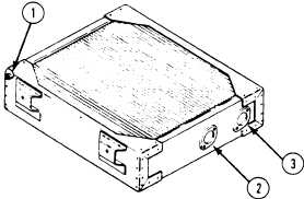
Plug auxiliary tank connection opening (1).
16.
Use radiator test plug set.
Connect water supply to radiator outlet
opening (2). Use radiator test stand.
17.
Flush radiator until water from radiator
inlet opening (3) runs clear.
18.
19.
20.
21.
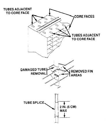
Resolder cracked solder joints and splice
damaged tubes. If necessary to repair tube
damage near end tanks, disassemble
radiator (steps 22 and 23).
Tube splicing shall be limited to no more
than two tubes adjacent to the core face on
either side.
Removed areas of fin shall not exceed 6-1/2
square inches (42 sq cm) per side, per any
tube repair. Length of tube splice shall not
exceed 2 inches ( 5 cm). Tube blockage is not
allowed.
Heat solder repair of the upper and lower
tanks, side brackets, and inlet and outlet
openings is allowed.
Heat soldering of a core shall not exceed a
linear length of 8 inches (20 cm) for any
one core assembly.
Fin straightening is allowed.
11.
12.
13.
14.
15.
TEST RADIATOR FOR FLOW
Plug auxiliary tank connection opening (1).
Use radiator test plug set.
Using radiator flow test machine, connect
supply hose to radiator inlet (3).
Connect return hose of test machine to
radiator outlet (2).
Flow test radiator at 70–80 gallons
( 276–292 liters) per minute. See
TM 750-254.
If pressure drop is more than 4 psi
(28 kPa), disassemble radiator and rod out
radiator core (see steps 22–30).
GO TO NEXT PAGE
5-3