TM 9-2350-261-20-2
R E P L A C E D R A I N C A P A N D S I G H T G A GE
INITIAL SETUP
Tools:
General Mechanics Tool Kit (Item 30, App D)
Torque Wrench (Item 99, App D)
Materials/Parts:
Antiseize compound (Item 4, App C)
Nonelectrical wire (Item 31, App C)
Packing (2)
Suitable container
Personnel Required:
Unit Mechanic
REMOVE
1.
2.
3.
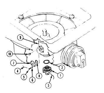
Place suitable container under drain cap (1).
Remove cap, packing (2) and lockwire (3),
and drain oil. Discard wire and packing.
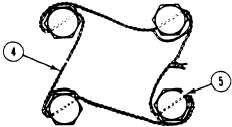
Remove lockwire (4), four screws (5), washers
(6), cover (7) and packing (8) from fan
gearbox (9). Discard lockwire and packing.
Remove filler plug (10) from fan gearbox (9).
INSTALL
4.
5.
6.
7.
8.
9.
10.
Install new packing (2) in fan gearbox (9).
Install drain cap (1) on fan gearbox (9).
Install new lockwire (3) through drain cap (1)
and fan gearbox (9). Twist lockwire.
Apply antiseize compound to threads of
screws (5) and plug (10).
Fill fan gearbox with oil.
Install plug (10) in fan gearbox (9).
Install new packing (8) and cover (7) on fan
gearbox (9). Secure with four washers (6) and
screws (5). Tighten screws to 42-48 in–lb
(4.7–5.4 N-m) torque. Use torque wrench.
References:
See your - 10
See your LO
Equipment Conditions:
Engine stopped/shutdown (see your -10)
Power plant rear access panel removed
(page 24-27 or 24-29)
Carrier blocked (see your –10)
11. Secure four screws (5) with new
lockwire (4). Double twist lockwire as shown
below.
8-42