TM 9-2350-261-20-2
INSTALL
10.
11.
12.
13.
14.
15.
16.
17.
18.
19.
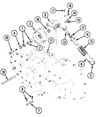
Install two bearings (1) and spacer (2) in
pulley (3), Secure with two retaining
rings (4). Use snap ring pliers.
Install new decal (5) (page 24-217) on
adjusting sleeve (6) if required.
Secure sleeve (6) to transfer gearcase with
straight pin (7) and two new cotter pins (8).
Secure idler pulley arm (9) to transfer gear-
case with straight pin (10) and new cotter
pin (11).
Install nut (12) on rod end (13).
Install adjusting nut (14) and spring (15) on
sleeve (6).
Install rod end (13) in nut (14).
Secure rod end (13) to idler pulley arm (9)
with pin (16) and new cotter pin (17).
Secure fan idler pulley (3) to arm (9) with
nut (18), washer (19), and bolt (20).
Tighten nut to 50-55 lb-ft (68-75 N-m)
torque. Use torque wrench.
Install and adjust fan drive belts
(page 8-35).
FOLLOW-THROUGH STEPS
1. Start engine (see your -10). Check adjustable
3. Engine stopped/shutdown (see your -10).
idler and fan drive belts for proper operation.
4. Install power plant rear access panel
2. Raise and lock ramp (see your -10).
(page 24-27 or 24-29).
END OF TASK
8-40