TM 9-2350-261-20-2
INSTALL
7.
8.
9.
10.
11.
12.
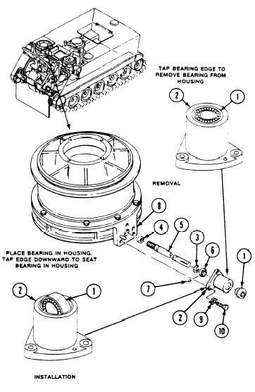
Install bearing (1) in housing (2) and tap
outer edge of bearing until seated in
housing.
Install new lockring (3) and new packing (4)
on drive shaft (5). Use snap ring pliers.
Slide collar (6), housing (2) and bearing (1)
to lockring (3) on drive shaft (5).
Turn collar (6) onto bearing (1) to lock
bearing to drive shaft (5), Tighten
setscrew (7) in collar (6).
Align splines and install drive shaft (5)
through support (8) opening into fan gear-
box.
Secure housing (2) to support (8) with three
new key washers (9) and screws (10).
Tighten screws to 300-360 lb-in
(34-41 N-m) torque. Use torque wrench.
FOLLOW-THROUGH STEPS
1. Install fan
2. Install fan
3. Install fan
4. Adjust fan
pulley (page 8-41).
6.
drive belts (page 8-35).
‘7.
pulley access cover (page 8-41).
drive belt tension (page 8-35).
8.
5. Install power plant rear access panel
(page 24-27 or 24-29).
9.
Install personnel heater (M106A2 and
M125A2 only) (page 28-52).
Install front ammunition rack (M106A2 and
M125A2 only) (page 24-188).
Raise and lock ramp (see your -10).
Stop/shutdown engine (see your -10).
END OF TASK
8-47 (8-48 blank)