TM 9-2350-261-20-2
R E P L A C E F A N D R I V E A D J U S T A B L E I D L E R A N D P U L L EY
DESCRIPTION
This task covers:
Remove (page 8-39).
Install (page 8-40).
INITIAL SETUP
Tools:
General Mechanics Tool Kit (Item 30, App D)
Snap ring pliers (Item 45, App D)
Torque wrench (Item 97, App D)
Materials/Parts:
Cotter pin (4)
Personnel Required:
Unit Mechanic
References:
See your -10
Equipment Conditions:
Engine stopped/shutdown (see your -10)
Carrier blocked (see your -10)
Ramp lowered (see your -10)
Power plant rear access panel removed
(page 24-27 or 24-29)
1.
2.
3.
4.
5.
6.
7.
8.
9.
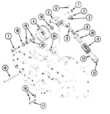
Remove fan drive belts (page 8-35).
Remove bolt (1), nut (2), washer (3), and fan
idler pulley (4) from idler pulley arm (5).
Remove cotter pin (6), headed pin (7), and
adjustable rod end (8) from idler pulley
arm (5). Discard cotter pin.
Loosen nut (9). Remove rod end (8) and
nut (9) from adjusting nut (10),
Remove nut (10) and spring (11) from
adjusting sleeve (12).
Remove decal (13) from adjusting sleeve (12)
only if replacement is required.
Remove cotter pin (14), straight pin (15), and
arm (5) from transfer gearcase. Discard cot-
ter pin.
Remove two cotter pins (16), straight pin
(17), and sleeve (12) from transfer gearcase.
Discard cotter pins.
Remove two retaining rings (18), bear-
ings (19), and spacer (20) from pulley (4).
GO TO NEXT PAGE
8-39