TM 9-2350-261-20-2
R E P L A C E F A N D R I V E P U L L E Y A N D A C C E S S C O V E R
INITIAL SETUP
Tools:
References:
General Mechanics Tool Kit (Item 30, App D)
see your -10
Torque Wrench Adapter (Item 9, App D)
Torque Wrench (Item 95, App D)
Equipment Conditions:
Materials/Parts:
Engine stopped/shutdown (see your -10)
Carrier blocked (see your -10)
Lockwasher (4)
Power plant rear access panel removed
(page 24-27 or 24-29)
Personnel Required:
Unit Mechanic
R E M O VE
7. Using torque wrench adapter, tighten nut (5)
to 300-360 lb-in (34-41 N•m) torque. Use
1.
2.
3.
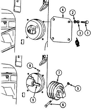
Remove four screws (1), flat washers (2),
lockwashers (3), and fan pulley access
cover (4) from power plant compartment rear
bulkhead. Discard l&washers.
torque wrench.
8. Secure cover (4) to power plant compartment
rear bulkbead with four flat washers (2), new
lockwashers (3), and screws (1).
Remove fan drive belts (page 8-35).
Remove nut (5), screw (6), pulley (7), and
key (8) from shaft (9).
INSTALL
4.
5.
6.
NOTE
-Place pulley (7) on fan shaft (9) with the
bolt and nut facing down as shown. Install
key (8) making sure key is flush with ends
of pulley and fan shaft. This will insure
proper alignment and pulley balance.
Install key (8) and pulley (7) on fan shaft
(9). Secure with screw (6) and nut (5) in
pulley hub. Do not tighten nut (5) at this
time.
Install and adjust fan drive belts
(page 8-35).
Align groove of pulley (7) with grooves of
idler pulley and fan drive pulley.
FOLLOW-THROUGH STEPS
1. Install power plant rear access panel
(page 24-27 or 24-29).
END OF TASK
Change 4
8-41