TM 9-2350-261-20-2
R E P L A C E A U X I L I A R Y T A N K T O C O O L A N T P U M P T U BE
INITIAL SETUP
Tools:
References:
General Mechanic’s Tool Kit (Item 30, App D)
See your -10
Materials/Parts:
Equipment Conditions:
Sealing compound (Item 46, App C)
Engine stopped/shutdown (see your –10)
Carrier blocked (see your -10)
Personnel Required
Trim vane lowered and power plant front
Unit Mechanic
access door open (see your –10)
Drain cooling system (page 8-3)
REMOVE
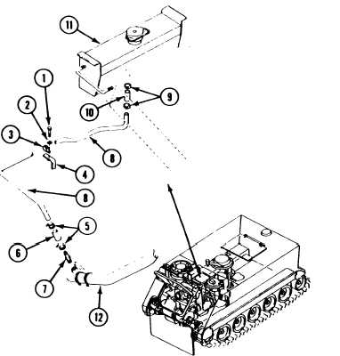
10. Secure hose (6) to tube (8) and adapter (7)
1.
2.
3.
4.
5.
with two clamps (5).
Remove screw (1), washer (2), and clamp (3)
from bracket (4).
11. Secure clamp (3) to bracket (4) with screw
(1) and washer (2).
Loosen two clamps (5). Disconnect hose (6)
from adapter (7) and tube (8).
Loosen two clamps (9). Disconnect hose (10)
from tube (8) and auxiliary tank (11).
Remove adapter (7) from oil cooler
Remove tube (8) from carrier, and
from tube.
INSTALL
6.
7.
8.
9.
eIbow (12).
clamp (3)
Apply a light even coat of sealing compound
to external threads of adapter (7).
Install adapter (7) in oil cooler eIbow (12).
Install clamp (3) on tube (8).
Secure hose (10) to auxiliary tank (11) and
to tube (8) with two clamps (9).
FOLLOW-THROUGH STEPS
1. Fill cooling system (page 8-5).
3. Stop/shutdown engine (see your -10).
2. Start engine (see your –10). Check for leaks.
4. Close power plant front access door and raise
trim vane (see your -10).
END OF TASK
8-30