TM 9-2350-261-20-2
14.
15.
16.
17.
18.
19.
20.
21.
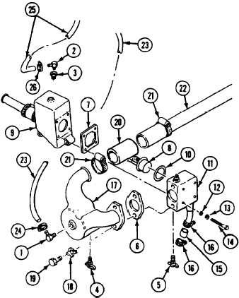
Install elbow (1) in deaeration elbow (17).
Secure hose (23) to elbow (1) with
clamp (24).
22. Install bushing (3) in housing (9).
23. Install elbow (2) in bushing (3).
Apply a light coat of sealing compound
(Item 51) to external threads of elbows
(1 and 2), bushing (31, and drain cocks
(4 and 5). Apply sealing compound
(Item 48) to both sides of gaskets
(6 and 7).
Install thermostat (8) and new gasket (7) in
thermostat housing (9).
Install seal (10) in cover (11). Secure
thermostat cover (11) to housing (9) with
four new washers (12), lockwashers (13),
and screws (14). Tighten screws to 180-240
lb-in (20-27 N•m) torque. Use torque
wrench and socket wrench set.
Connect hose (15) to cover (11) with two
clamps (16). Tighten clamps.
Secure deaeration elbow (17) and new
gasket (6) to cover (11) with two new key
washers (18) and screws (19).
Connect hose (20) to deaeration elbow (17)
and tube (21) with two clamps (22). Tighten
chimps.
24. Secure hose (25) to elbow (2) with
clamp (26).
25. Install drain cock (4) in deaeration elbow
(17) and drain cock (5) in housing
cover (11).
FOLLOW-THROUGH STEPS
1. Install air cleaner element and housing
(page 7-7)
4. Stop/shutdown engine (see your -10).
2. Fill cooling system (page 8-5).
3. Start engine (see your -10). Check for leaks.
5. Close power plant front access door and raise
trim vane (see your -10).
END OF TASK
Change 4
8-17