TM 9-2350-261-20-2
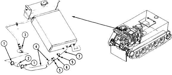
R E P L A C E R A D I A T O R O U T L E T E L B O W T O C O O L A N T P U MP
E L B O W H O S E A N D T U BE
INITIAL SETUP
Tools:
Equipment Conditions:
General Mechanics Tool Kit (Item 30, App D)
Engine stopped/shutdown (see your -10)
Carrier blocked (see your -10)
Personnel Required:
Driver’s power plant access panel removed
Unit Mechanic
(page 24-25)
Trim vane lowered and power plant front
References:
access door open (see your -10)
See your -10
Cooling system completely drained (page 8-3)
Air cleaner housing and element removed
(page 7-7)
REMOVE
1.
2.
3.
Remove two clamps (1) and hose
coolant pump elbow (3) and tube
Remove two clamps (5), hose (6)
from radiator outlet elbow (7).
INSTALL
(2) from
4.
(4).
and tube (4)
5.
Remove tube (4) through power plant front
6.
access door opening.
Install tube (4) through power plant front
access door opening.
Secure hose (2) to coolant pump elbow (3)
and tube (4) with two clamps (1).
Secure hose (6) to radiator outlet elbow (7)
and tube (4) with two clamps (5).
FOLLOW-THROUGH STEPS
1. Install air cleaner element and housing
4. Stop/shutdown engine (see your -10).
(page 7-7).
5. Install driver’s power plant access panel
2. Fill cooling system (page 8-5).
(page 24-25).
3. Start engine (see your -10). Check for leaks.
6. Close power plant front access door and raise
trim vane (see your -10).
END OF TASK
8-14