TM 9-2350-261-20-2
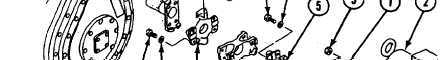
9. Secure adapter (1) to differential (2) with
four new locknuts (3). Tighten nuts to 75-80
lb-ft (102-108 N•m) torque. Use torque
wrench.
CAUTION
Final drive or differential damage could
result if universal joints and shaft are not
aligned right. Align and tighten all screws
to correct torque.
NOTE
Screws and washers must be clean, dry
and free of lubricants and paint. Washers
must be 5/32-inch (4 mm) hardened flat
steel only.
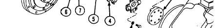
10. Position propeller shaft (4) in vise and in-
stall universal joints (5) with eight new
screws (6) and washers (7). Tighten screws
to 35-40 lb-ft torque. Use torque wrench
and adapter. Loosen screws and tighten
again to 35-40 lb-ft torque.
11. Position propeller shaft (4) with universal
joints (5) and secure to differential adapter
(1) and final drive yoke (8) with eight new
screws (9) and washers (10). Tighten screws
to 35-40 lb-ft torque. Use torque wrench
and adapter. Loosen screws and tighten
again to 35-40 lb-ft.
12. Deleted.
FOLLOW-THROUGH STEPS
1. Close power plant front access door and raise
2. Road test carrier (page 2-45) to check right
trim vane (see your -10).
final drive shaft.
3. Stop/shutdown engine (see your -10).
END OF TASK
20-8
Change 4