TM 9-2350-261-20-2
R E P L A C E R E A R B I L G E P U M P A N D S T R A I N E R
DESCRIPTION
This task covers:
Remove (page 16-8).
Clean, Inspect and Replace (page 16-9).
Install (page 16-9).
INITIAL SETUP
Tools:
General Mechanics Tool Kit (Item 30, App D)
Adjustable Wrench (Item 80, App D)
Materials/Parts:
Dry cleaning solvent (Item 13, App C)
Sealing compound (Adhesive)
(Item 52, App C)
Key washer (3)
Lockwasher (5)
Self-locking nut
Personnel Required:
Unit Mechanic
References:
See your -10
Equipment Conditions:
Engine stopped/shutdown (see your -10)
Ramp lowered (see your -10)
Battery ground lead disconnected (page 13-2)
Rear floor plate removed (page 24-36)
REMOVE
1.
2.
3.
4.
5.
6.
7.
8.
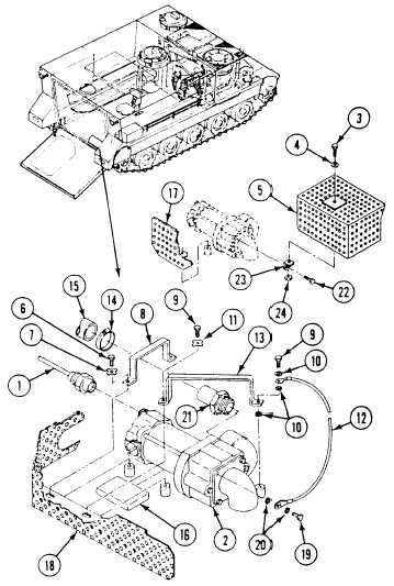
Disconnect circuit 451 lead (1) from rear bilge
pump (2).
On M106A2, M125A2, and M1064 only,
remove screw (3), washer (4), and strainer
(5) from pump (2).
Remove two screws (6), key washers (7), and
bracket (8) from hull weldnuts. Discard
washers.
Remove two screws (9), three lockwashers
(10), key washer (11), ground lead (12), and
bracket (13) from hull weldnuts. Discard
Iockwashers and key washers.
Loosen clamp (14). Remove pump (2) from
hose (15) and cushion (16).
Remove strainer (17) (M106A2, M125A2, or
M1064) or strainer (18) (all other carriers)
from hull weldnuts.
Remove screw (19), two Iockwashers (20),
ground lead (12), and adapter (21) from
pump (2). Use adjustable wrench. Discard
Iockwashers.
On M106A2, M125A2, and M1064 only,
remove screw (22), locknut (24), and bracket
(23) from pump (2). Discard locknut.
16-8
Change 2