TM 9-2350-261-34
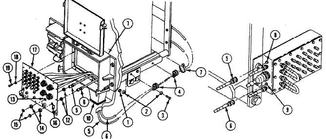
6. Remove two locknuts (1), four washers (2),
two screws (3), and clamps (4) from cables
W101 (5) and W102 (6). Discard locknuts.
11.
12.
7. Remove and discard straps (7) as required.
8. Disconnect cable W101, (5) from data panel
assembly A12, jack J1 (8), remove from
vehicle.
13.
9. Disconnect cable W102, (6) from data panel
assembly A12, jack J4 (9), remove from
vehicle.
INSTALL
10. Install cable W101, jack J103 (5) and/or
W102 jack J104 (6) in vehicle and route
through hole in hull top plate (10) up into
base of external communications box A11
(11). Have helper assist.
14.
15,
16.
Connect cable W101, (5) on data panel
assembly A12, jack J1 (8).
Connect cable W102, (6) on data panel
assembly A12, jack J4 (9).
Connect cable W101, jack J103 (5) with
inside bushing (12), on faceplate LAN A
(13) secure with outside bushing (14) and
jamnut (15).
Connect cable W102, jack J104 (6) with
inside bushing (12), on faceplate LAN B
(16) secure with outside bushing (14) and
jamnut (15).
Secure cable W101 (5) and/or W102 (6) to
hull with two clamps (4), screws (3), four
washers (2), and two new locknuts (1).
Secure slack in cable with new straps (7) as
required.
17. Install faceplate (17) on external
communications box A11 (11), secure with
fourteen new lockwashers (18), and screws
(19).
FOLLOW-THROUGH STEPS
1. Connect battery ground strap (see your -20).
3. Turn MASTER SWITCH OFF (see your -10).
2. Turn MASTER SWlTCH ON (see your -10).
Check that electrical system works properly.
END OF TASK
Change 4
21.1-57