TM 9-2350-261-34
ASSEMBLE
NOTE
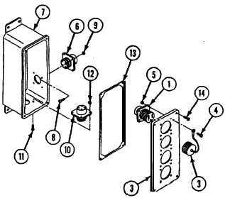
The four screws that secure connector J1
are shorter. Do not mix with other con-
nectors.
5. Install four connectors (1) on cover (2) with
dust caps (3) and secure with 16 screws (4)
and new locknuts (5).
6. Install connector J1 (6) on extension box (7)
and secure with four screws (8) and new
locknuts (9).
7. Install connector J6 (10) on extension box (7)
and secure with four screws (11) and new
locknuts (12).
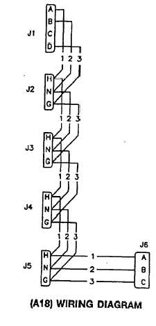
NOTE
See wiring diagram for assem-
ble/disassemble of wires to connectors.
8. Connect leads to connectors if necessary.
9. Install gasket (13) on extension box (7) with
cover (2) and secure with four screws (14).
FOLLOW-THROUGH STEPS
1. Install roadside AC power extension box A18
(see your -20).
END OF TASK
Change 4
21.1-53