TM 9-2350-261-34
ASSEMBLE
4. Install six connectors (1) on cover (2) with
dust caps (3) and secure with 24 screws (4)
and new locknuts (5).
5. Install connector J15 (6) on extension box (7)
and secure with four screws (8) and new
locknuts (9).
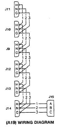
NOTE
See wiring diagram for assem-
ble/assemble of wires to connectors.
6. Connect leads to connectors if necessary.
7. Install gasket (10) on extension box (7) with
cover (2) and secure with four screws (11).
FOLLOW-THROUGH STEPS
1. Install curbside AC power extension box A19
(see your -20).
END OF TASK
Change 4
21.1-55