TM 9-2350-261-34
ASSEMBLE
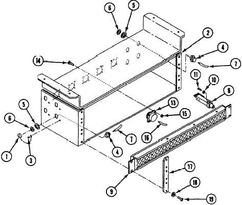
9. If dust caps (1) were removed, install dust
caps on signal patch panel box (2) and
secure with new rivets (3) .
12. Install five connecters J135, J136, J138,
J139, and J140 (13) on signal patch panel
box (2), secure with twenty screws (14) and
new locknuts (15).
NOTE
10. Install eight connectors (4) on signal patch
panel box (2), secure with lockwashers (5)
and jamnuts (6).
NOTE
Install wires (7) on eight connectors (4)
using wiring diagram (page 21.1-43).
Install wires (16) on five connectors J135,
J136, J138, J139, and J140 (13), using
wiring diagram (page 21.1-43).
13. Install three jackfields (9) on signal patch
panel box (2), secure with two strips (17),
twelve new lockwashers (18), and
screws (19).
Apply primer and sealant to threads of
screws (11).
11. Install 156 jacks (8) on three jackfields (9),
SECURE with new lockwashers (10) and
screws (11).
NOTE
Install two leads (12) on each jack (8)
using wiring diagram (page 21.1-43).
FOLLOW-THROUGH STEPS
1. Install signal patch panel box (see your -20).
END OF TASK
21.1-44
Change 4