TM 9-2350-261-34
R E P L A C E / R E P A I R I N V E R T E R A N D I N V E R T E R H O U S I N G
A S S E M B L Y A 2 ( M 1 0 6 8 O N L Y )
DESCRIPTION
This task covers:
Remove (page 21.1-9).
Clean, Inspect, and Repair (see Chapter 2).
Install (page 21.1-12).
INITIAL SETUP
Tools:
General ‘Mechanic’s Tool Kit (Item 35, App B)
Materials/Parts:
Lockwasher (12)
Lockwasher (6)
Lockwasher (4)
Self-locking nut (16)
Self-locking nut (8)
Self-locking nut (8)
Self-locking nut (4)
Self-locking nut (3)
Self-locking nut (2)
Personnel Required:
Power-Generation Equipment Repairer 52D10
Helper (H)
References:
see your -10
see your -20
TM 11-7010-256-12&P
Equipment Conditions:
Engine stopped (see your -10)
Carrier blocked (see your -10)
All external power disconnected
(TM 11-7010-256-12&P)
Battery ground lead disconnected
(see your -20)
Power control enclosure removed
(see your -20)
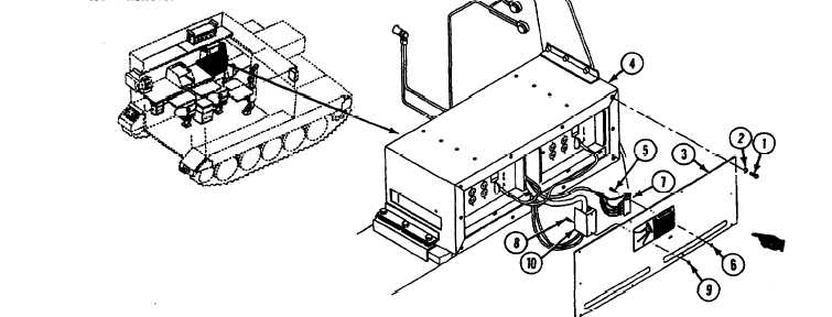
R E M O VE
NOTE
It is not necessary to remove the Housing
to remove one or both Inverters.
2. Remove four screws (5), locknuts (6), and ter-
minal block TB2 (7) from cover (3). Discard
locknuts.
3. Remove two screws (8), locknuts (9), and ter-
1. Remove ten screws (1), lockwashers (2), and
cover (3) from inverter housing (4). Discard
lockwashers.
minal block TB1 (10) from cover (3). Discard
locknuts.
GO TO NEXT PAGE
Change 4