TM 9-2350-261-34
A S S E M B LE
NOTE
See previous page for wiring diagram for
assemble/disassemble of wires to connec-
tors.
19.
20.
14.
15.
16.
17.
18.
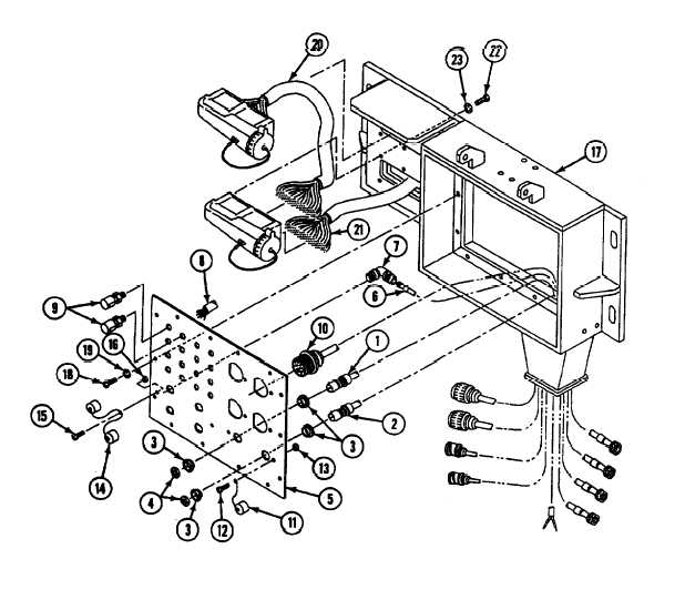
Install cable W101 (1), cable W102 (2) on
faceplate (5) and secure with four
21.
bushings (3) and two nuts (4).
Install four cables (6) and connectors (7) on
faceplate (5).
Connect cable W115 (8) to sixteen binding
posts (9).
Install four cables (10) on faceplate (5).
Install two cape (11) on faceplate (5) and
secure with two screws (12) and new
locknuts (13).
Install four caps (14) on faceplate (5) and
secure with two screws (15) and new
locknuts (16).
Install faceplate (5) on communication
box (17) and secure with fourteen
screws (18) and new lockwashers (19).
Install cable W117 (20) and cable
W118 (21) on communication box (19) and
secure with twelve screws (22) and new
lockwashers (23).
GO TO NEXT PAGE
Change 4
21.1-7