TM 9-2350-261-34
6.
7.
8.
NOTE
See following page for wiring diagram for
assemble/disassemble of wires to connec-
tors.
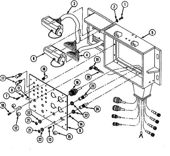
9. Remove two screws (13), locknuts (14), and
caps (15) from faceplate (9). Discard
locknuts.
Tag leads/cables before
removing/disconnecting. Replace pads
only if damaged.
10. Remove four cables (16) from faceplate (9).
11. Loosen sixteen binding posts (17) and
remove cable W115 (18).
Remove twelve screws (1), lockwashers (2),
cable W117 (3), and cable W118 (4) from
communication box (5). Discard lockwashers.
NOTE
If cable W118 is being replaced, remove
connector (6) before discarding.
12. Remove four connectors (19) and four
cables (20) from faceplate (9).
13. Remove two nuts (21), four bushings (22),
cable W101 (23), and cable W102 (24) from
faceplate (9).
Remove fourteen screws (7), lockwashers (8),
and faceplate (9) from communication box (5).
Discard lockwashers.
Remove two screws
four caps (12) from
locknut.
(10), locknuts (11), and
faceplate (9). Discard
GO TO NEXT PAGE
Change 4
21.1-5