TM 9-2350-261-34
NOTE
26.
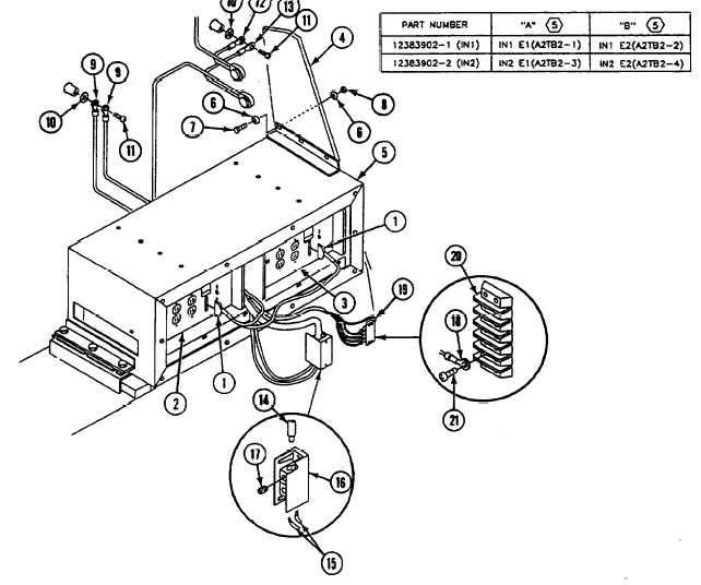
Before installation of inverters IN1 and
IN2, shut POWER switches OFF. The
cascade remote harness W15 will control
inverters.
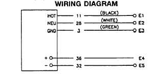
27.
Installation for inverters IN1 and IN2 are
different, follow schematic for proper
wiring connections:
28.
23.
24.
25.
Connect two cable W15 connectors (1) to
inverter IN1 (2) and inverter IN2 (3).
Install blackout curtain (4) on inverter hous-
ing (5) and secure with six washers (6),
three screws (7), and new locknuts (8).
Install two ground leads E5 (9) on carrier
wall and secure with new lockwasher (10),
Install ground lead W432 (12) and ground
lead W632 (13) on carrier wall and secure
with new lockwasher (10) and screw (11).
Connect Cable W6 (14) and two leads
E4 (15) on terminal block TB1 (16) and se-
cure with two set screws (17).
Connect cable W5 (18) and six leads (19) on
terminal block TB2 (20) and secure with ten
screws (21).
and screw (11).
GO TO NEXT PAGE
Change 4
21.1-13