TM 9-2350-261-34
R E P A I R P O W E R E N T R Y B O X A S S E M B L Y A 4 ( M 1 0 6 8 O N L Y )
DESCRIPTION
This task covers:
Disassemble (page 21.1-2).
Assemble (page 21.1-3).
Clean, Inspect, and Repair bee Chapter 2).
INITIAL SETUP
Tools
Personnel Required:
General Mechanic’s Tool Kit (Item 35, App B)
Power-Generation Equipment Repairer 52D10
Materials/Parts:
References:
Locknut (8)
Lockwasher
see your -20
Equipment Conditions:
Power entry box removed (see your -20)
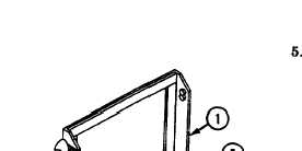
D I S A S S E M B LE
1. Open lid (1) to access faceplate (2).
4. Remove four screws (10), cap and chain (11),
locknuts (12), and cable W13 (13) from
EXTERNAL POWER IN hole on
faceplate (2). Discard locknuts.
2. Remove six screws (3), washers (4), and
faceplate (2) from power entry box (5).
3. Remove four screws (6), cap and chain (7),
locknuts (8), and cable W14 (9) from AC
POWER OUT hole on faceplate (2). Discard
NOTE
Tag all leads before removing from
-
terminals.
Remove wingnut (14), two washers (15),
nut (16), lockwasher (17), screw (18), and
five leads (19) from faceplate (2). Discard
lo&washer.
locknuts.
21.1-2
Change 4