TM 9-2350-261-34
TEST
111. Place main light selector switch in B.O.
102.
103.
104.
105.
106.
107.
108.
109.
110.
Connect battery ground lead
(see your -20).
Turn MASTER SWITCH ON
(see yOUr -10).
Place main light selector switch in STOP
or SER DRIVE position.
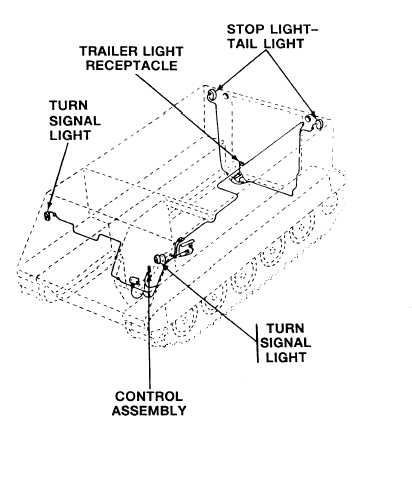
Move control lever to the left. Check left
front turn signal light and left rear stop
light–tail light. The light on the control
lever, the left front turn signal light, and
the left stop light-tail light should flash
on–and-off.
Use a multimeter to check for 24 volts
on-and-off at pin B of the trailer
receptacle.
Move control lever to the right. Check right
front turn signal light and right rear stop
light-tail light. The tight on the control
lever, the front signal light, and the right
stop light-tail light should flash on–and-off.
Use multimeter to check for 24 volts at
pin J of the trailer wiring harness
receptacle.
Lift stop on control lever and move lever to
extreme left. The light on the control lever,
both front turn signal lights, and both rear
stop light-tail lights should flash
on-and-off.
Use multimeter to check for 24 volts
on-and-off at pin B of the trailer
receptacle.
DRIVE position and infrared–blackout
selecting switch in B.O. position. The front
blackout marker lights, blackout headlight,
and blackout marker lights in the tail
lights should come on. The blackout stop
lights should come on when both
differential steering levers are pulled to
brake the earner.
FOLLOW-THROUGH STEPS
1. Install commander’s seat (see your –20).
4. Stop engine (see your –10).
2. Install rear compartment floor plates
5. Close power plant front door and raise trim
(see your -20).
vane (see your –10).
3. Raise and lock ramp (see your –10).
21-14
END OF TASK
[)1