T M
34.
35.
36.
37.
38.
39.
9-2350-261-34
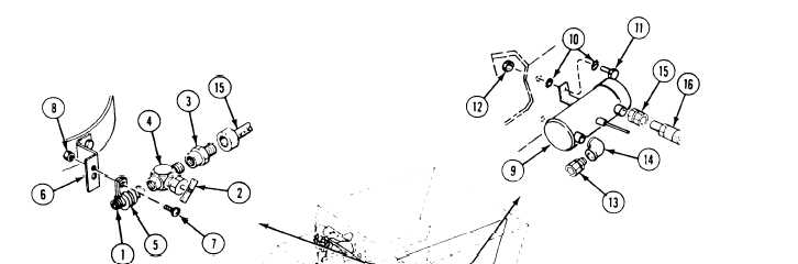
Apply a thin, even coat of primer and then
sealing compound (item 68) to external
tapered threads of nipple (1) and shutoff
cock (2). Do not apply primer or sealing
compound beyond small end of threads.
Install nipple (1), fuel shutoff cock (2), and
fuel pump inlet hose adapter (3) in tee (4).
Install clamp (5) on nipple (1). Secure
clamp (5) to bracket (6) with screw (7) and
nut (8).
Place electronic equipment heater fuel
pump (9) on center floor support beam near
rear of carrier. Secure with four
washers (10), two screws (11), and two
nuts (12).
Apply a thin, even coat of primer and then
sealing compound (item 68) to external pipe
threads of adapter (13). Do not apply
primer or sealing compound beyond small
end of threads.
Install outlet elbow (14) and outlet
adapter (13) on fuel pump (9).
40.
41.
42.
43.
44.
45.
46.
47.
Install fuel pump inlet adapter (15) on fuel
pump (9).
Connect inlet hose (16) to inlet hose
adapter (3) and inlet adapter (15).
Install clamp (17) on inlet hose (16).
Place fuel pump capacitor (18), fuel hose
clamp (17), wiring harness clamp (19), and
two washers (20) on hull weldnut (21).
Secure with new screw (22).
Lubricate rubber to rubber mating surfaces
with silicone paste.
Connect circuit 402A lead (23) to capacitor
lead (24).
Install clamp (25) on inlet hose (16).
Place fuel hose clamp (25) and wiring
harness clamp (26) on hull weldnut (27).
Secure with screw (28).
13-6