TM 9-2350-261-20-2
ASSEMBLE
14.
15.
16.
17.
18.
19.
20.
21.
22.
23.
24.
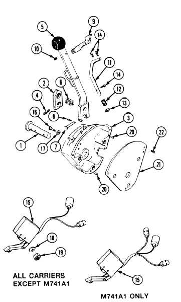
Install shaft (1) and cam (2) in housing (3).
Secure cam to shaft with new spring
pin (4).
Install control lever assembly (5) and spring
(6) in housing (3). Secure control lever to
shaft (1) with pin (7) and new cotter
pin (8).
Install lock (9) on control lever (5). Secure
with new spring pin (10).
Install control rod (11), spring (12), and
washer (13) in control lever (5).
Secure rod (11) to lock (9) and lever (5)
with three new cotter pins (14).
Install neutral start switch (15) in housing
(3). Secure with two screws (16), washers
(17), new lockwashers (18), and nuts (19).
Install two pins (20) in housing (3).
Secure cover (21) to housing (3) with two
screws (22).
Install range selector in carrier
(page 23-48).
Adjust range selector linkage (page 23-55).
Adjust neutral start switch (page 23-53).
FOLLOW-THROUGH STEPS
1. Install driver’s power plant access panel
3. Raise and lock ramp (see your -10).
(page 24-25).
4. Operate earner (see your -10). Check that
2. Close power plant front access door and raise
transmission range selector operates properly.
trim vane (see your -10).
5. Stop/shutdown engine (see your -10).
END OF TASK
23-52