TM 9-2350-261-20-2
17.
18.
19.
20.
21.
22.
23.
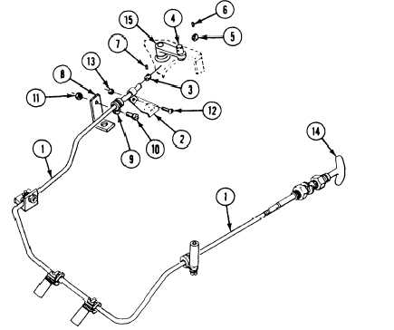
Insert control assembly (1) through engine
bracket (2).
Install rear collar (3) on control
assembly (1).
Insert control assembly (1) through pin (4).
Install front collar (5) on control
assembly (1).
Secure collars (3 and 5) on control
assembly (1) with two set screws (6 and 7).
Install control assembly (1) on engine
bracket (8). Secure with clamp (9),
screw (10), and new locknut (11).
Install control assembly (1) on engine
bracket (2). Secure with screw (12) and new
ADJUST
24.
25.
26.
27.
locknut (13).
Loosen two
(3 and 5).
Pull control
position.
Rotate fuel
position.
set screws (6 and 7) in collars
assembly handle (14) to full out
control arm (15) to full clockwise
Place two collars (3 and 5) on each side of
pin (4). Secure with two set screws
(6 and 7).
FOLLOW-THROUGH STEPS
1. Install power plant rear access panel
3. Close power plant front access door and raise
(page 24-27) or (page 24-29).
trim vane (see your –10).
2. Start engine (see your -10). Check that fuel
4. Raise and lock ramp (see your -10).
shutoff cable operates properly.
5. Stop/shutdown engine (see your –10).
END OF TASK
23-46
Change 1