TM 9-2350-261-20-2
R E P L A C E H A N D T H R O T T L E
DESCRIPTION
This task covers:
Remove (page 23-42).
Install (page 23-43).
Adjust (page 23-43).
INITIAL SETUP
Tools:
References:
General Mechanics Tool Kit (Item 30, App D)
See your -10
Materials/Parts:
Equipment Conditions:
Cotter pin
Engine stopped/shutdown (see your -10)
Grommet
Carrier blocked (see your -10)
Lockwasher
Trim vane lowered (see your -10)
Self-locking nut
Power plant front access door opened
(see your -10)
Personnel Required:
Driver’s power plant access panel removed
Unit Mechanic
(see your -10)
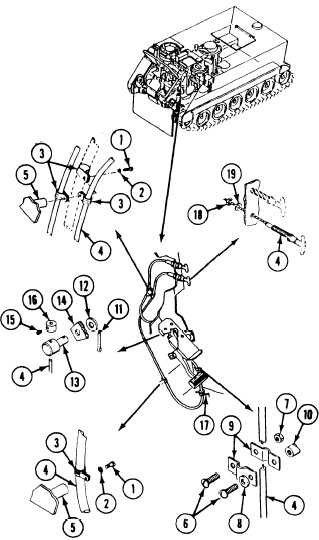
REMOVE
1.
2.
3.
4.
5.
6.
7.
Remove two screws (1), washers (2), and four
clamps (3) that secure throttle control cable
assembly (4) to two weldnuts (5).
Remove two screws (6), one locknut (7),
Iockwasher (8), two straps (9), and cable
assembly (4) from weldnut (10). Discard
locknut and lockwasher.
Remove cotter pin (11) and washer (12).
Disconnect pin (13) from accelerator pedal
assembly (14). Discard cotter pin.
Loosen set screw (15). Remove collar (16)
and pin (13) from cable assembly (4).
Pull cable assembly (4) through grommet (17)
in driver’s floor plate and out through power
plant front access door opening. Discard
grommet.
Remove nut (18) and washer (19) that secure
cable assembly (4) to driver’s compartment
bulkhead.
Remove cable assembly (4) from driver’s
compartment
23-42