TM 9-2350-261-20-2
5.
6.
CLEAN, INSPECT, AND REPLACE
4. Check torsion bar anchor and pins for wear
and damage. Replace if needed.
I N S T A LL
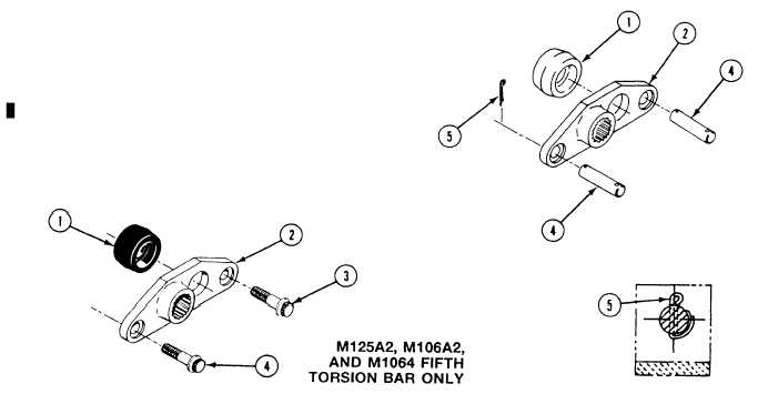
N O T E
Preformed packing (1) is installed on
third, fourth, and fifth anchor on all
carriers except M741A1. Preformed pack-
ing is not required on the M741A1.
Place new preformed packing (1) and torsion
bar anchor (2) on hull mount.
Install two screws (3) in anchor (2) on fifth
torsion bar anchor (M106A2, M1064, and
M125A2 only). Tighten screws to 320-330
Ib-ft (434-447 N·m) torque. Use torque
wrench.
7.
8.
On all other carriers and torsion bar posi-
tions, install two pins (4) in anchor (2). Se-
cure pins with two new cotter pins (5). Bend
pins as shown.
N O T E
Cotter pins must not prevent 360 degree
rotation of anchor pins.
Bend cotter pins (5) so they allow 360 degree
rotation of anchor pins.
FOLLOW-THROUGH STEPS
1. Install torsion bar (page 22-32).
5.
2. Install power plant (page 5-12) for second
torsion bar anchor, right side only.
6.
3. Install road wheel (page 22-7).
7.
4. Install track shroud and covers (page 22-2).
Remove blocks used to keep carrier from mov-
ing (see your -10).
Road test earner (page 2-101) to check that
torsion bar anchor is installed properly.
Stop/shutdown engine (see your -10).
END OF TASK
Change 2
22-37 (22-38 blank)