TM 9-2350-261-20-2
I N S T A LL
CAUTION
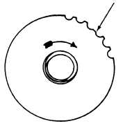
When removing or installing torsion bars,
the index or missing tooth on the anchor
end of torsion bar must align with index
on spline in road wheel arm, to allow bar
to pass through.
Align index or missing tooth on end of
torsion bar with index on road wheel arm
and torsion bar anchor before installing.
INDEX TOOTH
9. Thread puller with adapter and screw into
torsion bar.
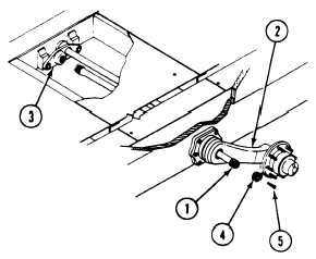
10. Install torsion bar (1) through road wheel
arm (2) and anchor (3). (H) Guide torsion
bar into anchor to ensure proper alignment.
Use slide hammer on puller to seat torsion
bar.
11. Remove puller and adapter from torsion bar.
12. Put a light coat of grease on threads of
plug (4) (see your LO). Install plug
in road wheel arm (2).
13. Tighten plug (4) to 50-75 lb-ft
(68-102 N·m) torque. Use torque wrench
and plug wrench.
14. Install screw (5) in plug (4).
N O T E
You may need to jack carrier, to raise
road arm, before positioning road wheel
lifter.
15. Position road wheel lifter (page 22-7).
C A U T I ON
Handle torsion bar with care. Do not tear
or cut wrapping.
N O T E
Left and right torsion bars are not inter-
changeable. To determine correct bar,
place arrow on end of torsion bar out-
board, with arrow at top. Arrow must
point toward front of earner.
22-34