TM 9-2350-261-20-2
5.
6.
7.
8.
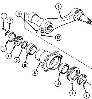
Remove six screws (l), three washers (2),
seal (3), retainer (4), and gasket (5) from
housing (6). Discard washers, seal and
gasket.
Remove support arm (7), seal (8), and
spacer (9) from housing (6). Discard seal.
If needed, remove two bearings (10) from
housing (6).
Remove lubrication fitting (11) and relief
C L E A N , I N S P E C T , A N D R E P L A C E
I N S T A L L
11. If removed,
housing (6)
install two bearings (10) in
Use replacer.
N O T E
Make sure shoulders on bearings point
toward center of housing.
12.
13.
14.
15.
16.
17.
18.
Coat threads of relief valve (12) and lubrica-
tion fitting (11) with sealing compound. In-
stall valve and fitting in support arm (7).
Put light coat of grease on bearing surface
of support arm (7) and cork–rubber face of
new seal (8). Place spacer (9) and seal, with
pins facing housing, on shaft of support
arm.
Install support arm (7) in housing (6). Align
pins on seal (8) with holes in housing (6).
Put light coat of sealing compound on outer
surface of new seal (3).
Install new gasket (5), retainer (4), and seal
(3) in rear of housing (6). Use replacer.
Secure with three new washers (2) and six
screws (1). Do not tighten screws at this
time.
Fill support arm housing (6) with grease
until grease appears around retainer (4).
Tighten six screws (1) to 168–228 lb-in
(19-26 N•m) torque. Use torque wrench
(Item 95, App D) . Bend tabs on new
washers (2).
9.
10.
Check fittings and relief valve for wear and
damage. Replace if needed.
Inspect bearings IAW TM 9-214. Replace if
needed.
—
GO TO NEXT PAGE
1>. -.--.-.1 k-- A---- -- —----.-J 1 ---- ~~n Kl\
Change 1
22-13
wmvannnnl uncI,
v a l v e ( 1 2 ) f r o m s u p p o r t a r m ( 7 ).