TM9-2350-261-20-2
R E P L A C E R O A D W H E E L S U P P O R T A R M , B E A R I N G S , A N D
S E A L S
D E S C R I P T I O N
This task covers:
Remove (page 22-12).
Clean, Inspect, And Replace (page 22-13).
Install (page 22-13).
I N I T I A L S E T U P
Tools:
General Mechanics Tool Kit (Item 30, App D)
Replacer (Item 56, App D)
Socket Wrench Set (Item 89, App D)
Torque Wrench (Item 95, App D)
Torque Wrench (Item 96, App D)
Materials/Parts:
Grease (Item 18, App C)
Sealing compound (Item 47, App C)
Bearing (2)
Inner seal
Outer seal
Packing
Retainer gasket
Key washer (3)
Personnel Required:
Unit Mechanic
References:
See your -10
See your -12
Equipment Conditions:
Carrier on level surface
Engine stopped/shutdown (see your -10)
Carrier blocked (see your -10)
Track shroud and covers removed (page 22-2)
Road wheel removed (page 22-7)
Road wheel hub removed (page 22-9)
Shock absorber removed from first, second, or
fifth road wheel (page 22-26)
Torsion bar removed (page 22-32)
R E M O V E
1.
2.
3.
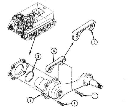
Remove six screws (1), road wheel arm as-
sembly (2) (number one and two positions)
and packing (3) (All except M741A1).
Remove two screws (l), four screws (4), road
wheel support arm assembly (2), packing (3),
and guard (5) from hull (number three posi-
tion) (All except M741A1).
N O T E
Guard (5) used as support arm position
three, is different from guard (6), used at
support arm positions four and five. Do
not interchange guards.
Remove two screws (1), four screws (4), road
wheel support arm assembly (2), packing (3),
and guard (5) from hull (number four and
five positions) (All except M741A1). Discard
packing.
4. Remove six screws (1) (number one position),
five screws (number two, three, four, and five
positions), road wheel support arm assembly,
(2) and packing (3) from hull (M741A1 only).
22-12
Change 1


