TM9-2350-261-20-2
19.
20.
21.
22.
23.
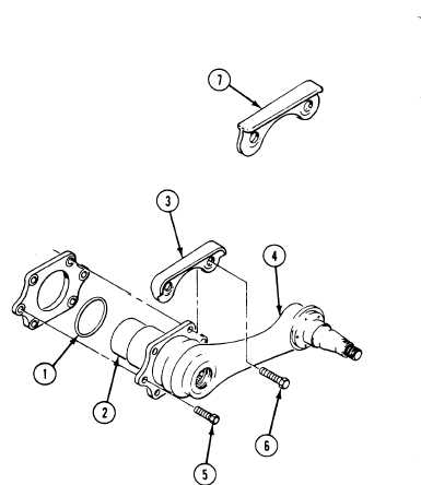
Install new packing (1) on assembly (2).
Secure guard (3), packing (l), and assem-
bled road wheel support arm assembly (4) to
hull (number four and five positions) with
four screws (5) and two screws (6). Tighten
six screws to 130–140 lb-ft (176-190 N•m)
torque. Use torque wrench (Item 96) (All
except M741A1.)
Secure guard (7), packing (1) and assembled
road wheel support arm assembly (4) to hull
(number three position) with four screws (5)
and two screws (6). Tighten SiX screws to
130-140 lb-ft (176–190 N•m) torque. Use
torque wrench (Item 96) (All except
M741A1.)
Secure assembled road wheel support arm
(4) to hull (number one positions) with six
screws (6). Tighten screws to 130-140 lb-ft
(176-190 N•m) torque. Use torque wrench.
(Item 96) All except M741A1.)
Secure assembled road wheel support arm
(4) to hull (number two, three, four, and
five positions) with five screws (5). Use SiX
screws (number one position). Tighten
screws to 130-140 lb-ft (176-190 N•m)
torque. Use torque wrench (Item 96)
(M741A1 only.)
F O L L O W - T H R O U G H S T E PS
1. Install torsion bar (page 22-32).
5.
2. If removed, install shock absorber
6.
(page 22-26).
7.
3. Install road wheel hub (page 22-9).
4. Install road wheel (page 22-7).
8.
Lube road wheel supports (see your LO).
Install track shroud and covers (page 22-2).
Remove blocks used to keep carrier from mov-
ing (see your -10).
Road test carrier (page 2-91) to check that
arm is installed properly.
END OF TASK
22-14
Change 1