TM 9-2350-261-20-2
REPAIR RECEPTACLE
DESCRIPTION
This task covers:
Remove (page 14-7).
Install (page 14-8).
INITIAL SETUP
Tools:
General Mechanics Tool Kit (Item 30, App D)
Soldering Gun (Item 34, App D)
Digital Multimeter (Item 43, App D)
Electrical Tool Kit (Item 75, App D)
Materials/Parts:
Insulation sleeving (Item 21 thru 25, App C)
Solder (Item 57, App C)
REMOVE
CLEAN, INSPECT, AND REPAIR
Personnel Required:
Unit Mechanic
References:
See your -10
See your -24P
Equipment Conditions:
Engine stopped/shutdown (see your -10)
Battery ground lead disconnected (page 13-2)
Carrier blocked (see your -10)
1.
2.
3.
4.
N O T E
5.
Use same procedure for repairing single
or multiple lead, and male or female
receptacle.
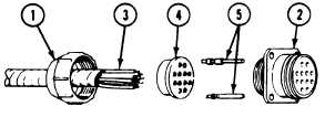
Loosen nut (1) from receptacle (2). Slide nut
back on leads (3).
6.
Remove grommet (4) with contacts (5) from
rear of receptacle (2).
7.
Push leads (3) into grommet (4) until
contacts (5) are fully exposed on other side of
grommet. Remove grommet (4) and nut (1)
from leads (3).
Clip or desolder leads from contacts. Use
soldering gun. Discard contacts.
Check wire leads. Look for damaged
insulation or broken wires. If wire leads have
been taped together, remove tape. Scrape wire
lead covering with your thumbnail to see if
covering peels off. Replace bad leads.
Check contact pins, contact sockets, and
terminals. Replace burned, bent, or broken
parts.
Check shells, sleeves, and nipples. Replace
cut, torn, or damaged parts.
GO TO NEXT PAGE
14-7