TM 9-2350-261-20-2
REPLACE DISTRIBUTION BOX ASSEMBLY FOR 100 AMP
GENERATOR SYSTEM (M113A2, M106A2, M125A2, M1064,
AND M1059 ONLY)
DESCRIPTION
This task covers:
Remove (page 12-44).
Install (page 12-46).
INITIAL SETUP
Tools:
General Mechanics Tool Kit (Item 30, App D)
Materials/Parts:
Sealing compound (Item 52, App C)
Gasket
Grommet (8)
Lockwasher (6)
Lockwasher (5)
Personnel Required:
Unit Mechanic
References:
See your -10
Equipment Conditions:
Engine stopped/shutdown (see your -10)
Carrier blocked (see your -10)
Battery ground lead disconnected (page
Master switch panel assembly removed
(page 9-16)
REMOVE
3.
1.
2.
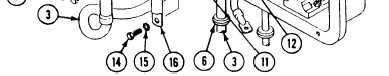
For M113A2 and M1059 earners, remove
screw (1), lockwasher (2), circuit 6 lead (3),
and circuit 6L lead (5) from bus bar (4).
Remove circuit 6 lead (3), circuit 6L lead (5),
and two grommets (6 and 7) from
distribution box (8). Discard grommets and
4.
lockwasher.
For M106A2, M1064, and M125A2 carriers,
remove screw (1), lockwasher (2), and circuit
6 lead (3) from bus bar (4). Remove circuit 6
lead (3) and grommet (6) from distribution
box (8). Discard grommet and lockwasher.
12-44
Change 2
13-2)
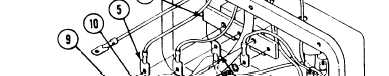
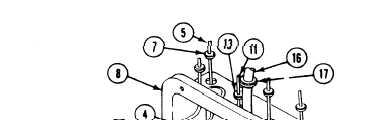
Remove screw (9), lockwasher (10), circuit 10,
14, 15, 27E lead (11), and circuit 450A lead
(12) from bus bar (4). Remove circuit 10, 14,
15, 27E lead (11) and grommet (13) from
distribution box (8). Discard grommet and
lockwasher.
Remove screw (14), lockwasher (15), and
circuit 49 lead (16) from bus bar (4). Remove
circuit 49 lead (16) and grommet (17) from
distribution box (8). Discard grommet and
lockwasher.