TM 9-2350-261-20-1
2.
3.
4.
5.
6.
7.
8.
9.
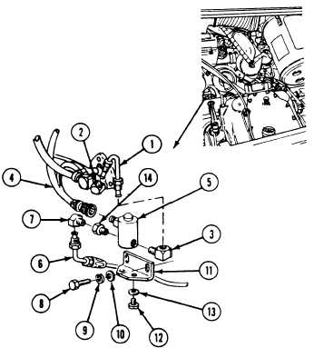
Disconnect fuel tube (1) from two elbows
(2 and 3).
Disconnect electrical lead (4) from solenoid
valve (5).
Disconnect fuel hose (6) from elbow (7).
Remove two screws (8), lockwashers (9), flat
washers (10), bracket (11), and solenoid valve
(5) from engine. Discard lockwashers.
Remove two screws (12), lockwashers (13),
and solenoid valve (5) from bracket (11).
Discard lockwashers.
Remove elbow (7) from adapter (14).
Remove adapter (14) from solenoid valve (5).
Remove elbow (3) from solenoid valve (5).
INSTALL
10.
11.
12.
13.
14.
15.
16.
17.
18.
Apply sealing compound to cleaned external
threads of fittings.
Install elbow (3) in solenoid valve (5).
Install adapter (14) and elbow (7) in
solenoid valve (5).
Secure solenoid valve (5) to bracket (11)
with two new lockwashers (13) and screws
(12).
Install bracket (11) and solenoid valve (5)
on engine. Secure with two flat washers
(10), new lockwashers (9), and screws (8).
Connect fuel hose
Connect electrical
valve (5).
Connect fuel tube
(6) to elbow (7).
lead (4) to solenoid
(1) to two
elbows (2 and 3).
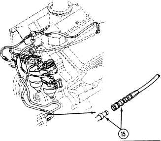
Connect fuel return hose quick-disconnect
coupling (15) .
FOLLOW-THROUGH STEPS
1. Connect battery ground lead (page 13-2).
2. Close power plant front access door and raise
trim vane (see your -10).
END OF TASK
6-137