TM 9-2350-287-20-1
7-16. HYDRAULIC CONTROL GAGE PANEL ASSEMBLY REPAIR (continued).
4.
5.
6.
7.
8.
9.
10.
11.
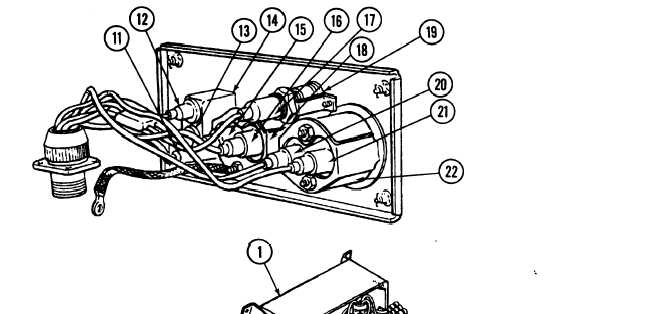
Disconnect electrical lead MB (12), electrical lead 10 (13), and electrical lead AAA (11) from rear of toggle
switch (14).
Disconnect electrical lead CD (15) and electrical lead 27 (16) from rear of oil level gage (18).
Disconnect electrical lead 40 (17) from rear of indicator light (1 9).
Disconnect electrical lead 664 (20) and electrical lead 27 (21) from rear of temperature gage (22).
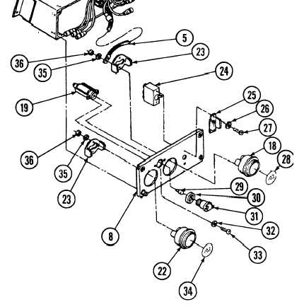
Remove four nuts (36) and
Iockwashers (35), ground lead (5),
and two mounting clamps (23)
securing oil level gage (18),
temperature gage (22), and two
lenses (28 and 34) to cover (8).
Discard Iockwashers.
Remove lens (31), preformed packing
(30), and bulb (29) from indicator light
(19). Discard preformed packing.
Remove two screws (33) and
Iockwashers (32) and indicator light
(19) from cover (8). Discard
Iockwashers.
Remove two screws (27) and
Iockwashers (26), toggle switch (24),
and guard (25) from cover (8). Discard
Iockwashers.
7-45