TM 9-2350-207-20-1
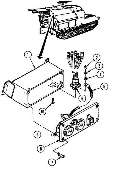
7-16. HYDRAULIC CONTROL GAGE PANEL ASSEMBLY REPAIR.
This Task Covers:
a. Disassembly
b. Assembly
Initial Setup:
Tools/Test Equipment:
l General mechanic’s tool kit (Item 24,
Appendix l)
Materials/Parts:
l Lockwasher (4) (Item 122, Appendix H)
l Lockwasher (4) (Item 160, Appendix H)
l Lockwasher (4) (Item 161, Appendix H)
l LockwWasher (4) (Item 189, Appendix H)
l Preformed packing (Item 240, Appendix H)
Equipment Conditions:
l Vehice parked on level ground (refer to
TM 9-2350-287-10).
l Hydraulic control panel assembly removed
(para 17-28).
a.
DISASSEMBLY
WARNING
When working on vehicle’s electrical
system, remove dogtags, rings, and
other jewelry. Disconnect batteries
by removing ground cables first.
Connect ground cables last when
connecting batteries.
1.
Turn four retaining studs (7) securing
cover (8) to control box body (1), and pull
cover (8) away from body (1).
2.
Remove four Iockwashers (9) and studs
(7) from cover (8). Discard Iockwashers.
NOTE
For proper assembly, note position
of ground lead attached to
connector and bottom hydraulic
control gage clamp stud.
3.
Remove four screws (10), Iockwashers
(3), washers (4), and nuts (2), ground
lead (5), and wiring harness 12333555
(6) from body (1). Discard Iockwashers.
7-44