TM 9-2350-287-20-1
4-28. ACCELERATOR, THROTTLE, AND ENGINE CONTROL GOVERNOR REPLACEMENT
AND ADJUSTMENT (continued).
5.
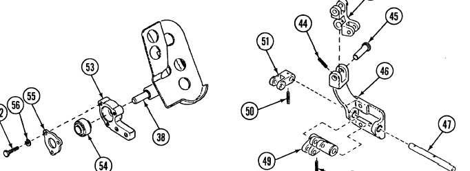
Install bearing (54) and cap (55) in accelerator bracket (53) with three screws (52) and new Iockwashers (56).
6.
Install accelerator bracket (53) on accelerator pedal assembly (38).
7.
8.
9.
10.
11.
Install two bellcranks(15 and 49) and pins (45 and 47) and lever (51 ) on throttle bracket (46).
Install new spring pin (44) and two new spring pins (48 and 50) on two pins (45 and 47).
NOTE
• Step 9 covers assembly of assembled rods (13 and 18) equipped with two rod ends each.
• Step 10 covers assembly of assembled rod (1), connecting link (8), and throttle rod assembly (32)
equipped with one rod end each.
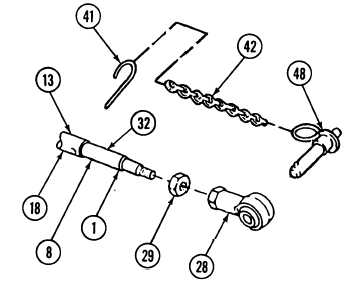
• Step 11 covers further assembly of connecting link (8) equipped with quick-release pin.
• Assembly of connecting link (8) equipped with quick-release pin is shown in drawing.
Install two nuts (29) and rod ends (28) on
each of two assembled rods (13 and 18). Do
not tighten nuts until final adjustment.
Install nut (29) and rod end (28) unassembled
rod (1), connecting link (8), and throttle rod
assembly (32). Do not tighten nut until final
adjustment.
Install quick-release pin (43), chain (42), and
new wire (41 ) on rod end (28) of connecting
link (8).
4-91