TM 9-2350-287-20-1
4-27. GLOW PLUG AND GLOW PLUG CONTROLLER REPLACEMENT.
This Task Covers:
a.
Removal
b.
Installation
Initial Setup:
Tools/Test Equipment:
Equipment Conditions:
General mechanic's tool kit
Vehicle parked on level ground
(Item 24, Appendix I)
(refer to TM 9-2350-287-10).
[Item Deleted]
Battery ground cables disconnected (para 7-42).
Exhaust pipe removed (for left-side glow plugs only)
Materials/Parts:
(para 5-2).
Air cleaner intake duct removed (for left-side glow
[Items Deleted]
plugs only) (para 4-9).
[Item Deleted]
Lockwasher (2) (Item 162, Appendix H)
Front hull slope plate removed (for right-side glow
Lockwasher (5) (Item 163, Appendix H)
plugs only) (refer to TM 9-2350-287-20-2).
a.
REMOVAL
NOTE
If replacing glow plug only, perform
steps 1 and 2.
1.
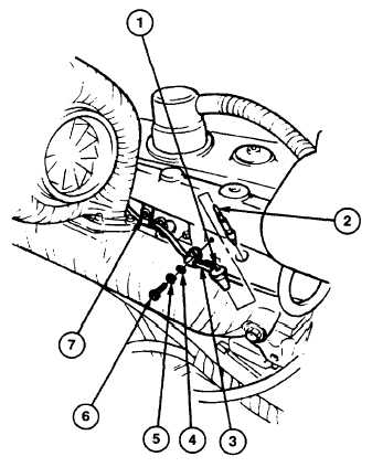
Disconnect eight wiring harness connectors (1)
from eight glow plugs (2).
2.
Remove glow plug (2) from engine.
3.
Remove five screws (6), lockwashers (5),
washers (4), and clamps (7) securing wiring
harness (3) to engine. Discard lockwashers.
Change 1 4-79