TM 9-2350-287-20-1
2-19. TROUBLESHOOTING CHART (continued).
o.
PERSONNEL VENTILATION BLOWER (continued).
(1) PERSONNEL VENTILATION BLOWER DOES
NOT OPERATE. All other electrical components
operate (continued).
CONTINUED FROM D
D. 9. Check for 24 ± 3 vdc.
10. Turn MASTER switch OFF (refer to TM 9-
2350-287-10).
Is voltage present on both circuits?
Repair wire 159C or replace harness
12351461 (para 7-79). Verify problem is
solved.
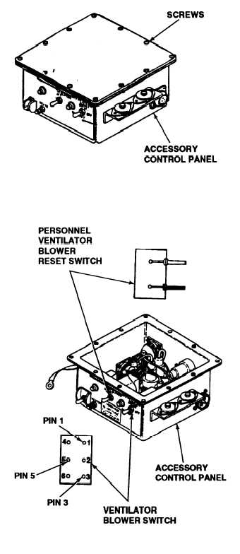
E. 1. Remove accessory control box (para 7-
10).
2. Remove 12 nuts, 12 Iockwashers, 12 flat
washers, 12 screws, cover and gasket from
control box.
3. Check ventilator blower switch for conti-
nuity of the lNTAKE circuit between pin 5 and
pin 1 with the switch in the up (INTAKE)
position.
4. Check ventilator blower switch for conti-
nuity of the EXHAUST circuit between pin 5
and pin 3 with the switch in the down (EX-
HAUST) position.
Is there continuity in both INTAKE and EXHAUST
circuits?
Replace ventilator blower switch (para 7-9).
Verify problem is solved.
F. Check PERSONNEL VENTILATOR BLOWER
RESET switch for continuity by placing red
lead of multimeter on first pin of switch and
black lead of muttimeter on remaining pin of
switch, toggle RESET switch.
Continued on next page
2-252