TM 9-2350-287-20-1
2-19. TROUBLESHOOTING CHART (continued).
o. PERSONNEL VENTILATION BLOWER (continued).
(1) PERSONNEL VENTILATION BLOWER DOES
NOT OPERATE. All other electrical components
operate (continued).
CONTINUED FROM B
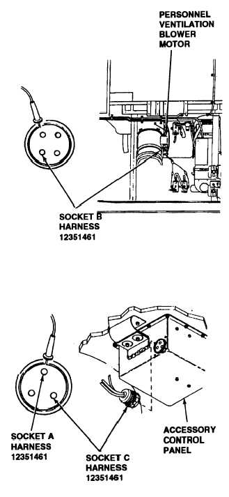
C. 1. Place red lead of multimeter in plug socket
B and ground black lead.
2. Turn MASTER switch ON (refer to TM 9-
2350-287-1 O).
3. Press PERSONNEL VENTILATOR
BLOWER toggle switch to INTAKE position.
4. Check for 24 ± 3 vdc.
Is voltage present in the intake circuit?
Replace personnel ventilator blower (para
7-81 ). Verify problem solved.
D. 1. Reconnect wiring harness 12351461 plug
to ventilation blower motor.
2. Disconnect wiring harness 12351461 plug
(circuits 159A, 159B, 159C) from accessory
control box.
3. Place red lead of multimeter in accessory
control box connector socket C and ground
black lead.
4. Turn MASTER switch ON (refer to TM 9-
2350-287-10).
5. Place PERSONNEL VENTILATOR
BLOWER switch in EXHAUST position.
6. Check for 24 ± 3 vdc.
7. Place red lead of multimeter in socket A
and ground black lead.
8. Place PERSONNEL VENTILATOR
BLOWER switch in the INTAKE position.
Continued on next page
2-251