TM 9-2350-287-20-1
2-19. TROUBLESHOOTING CHART (continued).
0. PERSONNEL VENTILATION BLOWER (continued).
(1) PERSONNEL VENTILATION BLOWER DOES
NOT OPERATE. All other electrical components
operate.
Initial Setup:
Tools/Test Equipment:
l Digital multimeter (DMM) (Item 13, Appendix 1)
l General mechanic’s tool kit (Item 24,
Appendix I)
STE/lCE test kit (Item 63, Appendix I)
Materials/Parts:
l Lockwashers (4) (Item 196, Appendix H)
Equipment Conditions:
l Crew AFES anti-recoil plugs installed
(para 21-4 and 21-5).
l Engine AFES T/A panel maintenance switch to
vertical position (refer to TM 9-2350-287-1 0).
Crew AFES T/A panel maintenance switch to
vertical position (refer to TM 9-2350-287-1 0).
l Safety pins installed in all AFES bottle actuators
(para 21-4 and 21-5).
l Left projectile rack moved to rear of vehicle
(refer to TM 9-2350-287-10).
NOTE
Instead of using multi meter
for voltage
check, STE/lCE
troubleshooting,
INDIVIDUAL
BATTERY VOLTAGE TEST-TEST
89 maybe performed.
Instead of using multi meter
for continuity check, STE/lCE
troubleshooting, TEST 91 may
be performed.
l STE/lCE test no. 89, Voltage checks,
and no. 91, continuity and resistance
checks, may be used as an alternate
troubleshooting method.
WARNING
Ventilation system and Automatic
Fire Extinguisher System (AFES)
electrical systems are inter-
connected.
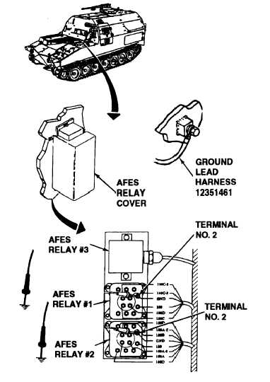
A. 1. Remove AFES relay covers by removing 4
screws, 4 washers, 4 Iockwashers and cover.
2. Check harness 12351461 ground at bulk-
head. Tighten screw to ensure good ground.
3. Using a multimeter, test grounds at the
following points.
Continued on next page
2-249