TM 9-2350-261-34
REPAIR CURBSIDE DC POWER EXTENSION BOX A8
(M1068 ONLY)
DESCRIPTION
This task covers: Disassemble (page 21.1-64).
Clean, Inspect, and Repair (see Chapter 2).
Assemble (page 21.1-65).
INITIAL SETUP
Tools:
References:
Automotive Fuel and Electrical System Repair
See your -20
Took Kit (Item 7, App B)
Equipment Conditions
Materials/Parts:
Curbside DC power extension box removed
Self-locking nut (20)
(see your -20)
Personnel Required:
Fuel and Elec Sys Rep 63G10
DISASSEMBLE
NOTE
See wiring diagram for assem-
ble/disassemble of wires to connectors.
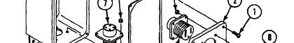
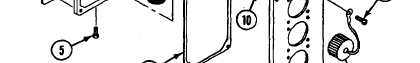
2. Remove four screws (5), locknuts (6), and
connector J1 (7) from extension box (4).
Discard locknuts.
3. Disconnect leads from connectors if necessary.
1. Remove four screws (1), cover (2) and
gasket (3), from extension box (4).
NOTE
4. Remove sixteen screws (8), locknuts (9), four
connectors (10) and dust caps (11) from
cover (4). Discard 1ocknuts.
Tag all leads before disconnecting for
proper assembly later.
21.1-64
Change 4